For use on the 6 meter band i have been searching for a while for a simple antenna for this band, for it's difficult to put
up an Yagi on my qth. So it had to be a omni directional or a kind of antenna that needs little space.
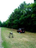
I came across the design of a J-antenna (picture one), but that was a failure because i could not peek the antenna in the band, and i expected trouble from the district council
for it's height. After that i tried a dipole, bud that didn't met up to my expectations.
Then i found a Delta loop design and i have constructed one, bud due to a low line-up of the antenna (shack height) i had a lot on distortion on the transmitter. After i put up
the antenna on the roof, i had no further problems.
 |
 |
 |
 |
 |
Click on the photo for a large version |
||||
Before i go in on the construction of the Delta loop, first some theory:
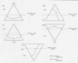
A Delta loop is configured as a equilateral triangle, on witch he base can be places at the top as well at the bottom and can be configured in several shapes (see picture 5).
Depending of it's shape the antenna radiates vertical of horizontal. The effective position of the Delta loop should be on a half wave length high above reflecting services, on that
point in the antenna where the radiation pont is half a wave (dotted lines in picture 5)
For DXing you can best chose the two vertical forms out of picture 5 namely the B type, with a radiation angle of 27o and the E type with a radiation angle of
20o, both vertical polarized.
The other types are all horizontal polarized, where the A and the C type have a radiation angle of 80o and find it's most use in the short distance
communication range
The D-type has a radiation angle of 47o and is useful for the mid range communication.
It is very important for considerations of the shape of the Delta loop that the feeding point should not be positioned in the radiation field of the antenna. If done so
it will effect the radiation patron AND functioning of the antenna in the sense of distortion.
The deviation in the radiation patron is for 1/3 in the two sloping sides and 2/3 in the horizontal side, and has a amplification of 1,5 a horizontal dipole.
Construction of the Delta loop
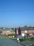
I have chosen the D version in picture 5 (see photo 2). The reason for this is that i wanted to operate an horizontal antenna, with an easy connection.
The dimensions of the Delta loop can be calculated by 306.3/f in Mhz. This will give the length for the used wire in meters.
For the 6 meter band that would be 306.3/50 = 6.13 meter of total length of the wire.
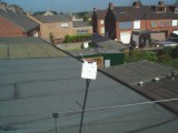
By theoretical dividing this length in 3 you get the shape op the Delta loop by putting the endings together (photo 3).
The impedance of a Delta loop is 100 Ohm. This can be adapted to 50 Ohm by a 1/4 lambda times the shortening factor of a 75 Ohm cable
(1/4 * 6,13 = 1,53 * 0.66 = 1,01 meter).
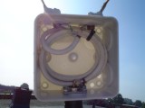
For convenience sake i have taken 1,1 meter of 75 Ohm television cable (i must connect it) and wind it on the hand. The reason for this is twofold, besides impedance
adapting in this manner we can use it also as choke for cable current. After this we put the choke in a waterproof casing. In my case i used a junction box for outside
cabling on witch i manufactured a cable chassis part and two bolds on top for the antenna wire.
BE SURE TO MAINTAIN ENOUGH DISTENCE BETWEEN THE BOULDS
The finishing touch is waterproofing the bolds with acid free silicone kitting.
Experience with the Delta loop (juli 2005)
I have put up the antenna between two masts and it's direction is east 300o. This means that the antenna is radiating towards north direction Hull in England and
towards south direction Venice Italia
The antenna has a standing wave ratio of 1:1 in the low part of the band (SSB section) and goes up to 1:1.4 at 51.1875 Mhz. NOT BAD !!!
This band is an band u must watch closely. There are times you can hear nothing bud mixing signals from television set's, when on other times you can work all around
Europe and beyond.
I have worked EA, YO, YU, IK0, I, SQ, LZ and many others, bud strangely no UK yet what wonders me.