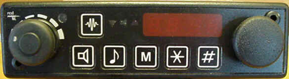
With the operation of this radio i encountered a problem that there is no lighting under the buttons. Specially in the dark that's a handicap.
To build in the lights you have to make some modifications, that i have explained in steps. By some of these steps i have made some pictures to make some things clearer. If you click on these little pictures there opens up a bigger picture in a separate screen
1 st step: Loosen the head and take it apart
2 th step: Take apart the boards
3 th step: Drill holes for the led's
4 th step: Solder the led's
5 th step: Power feeds to the led's
6 th step: Put the head together again
7 th step: Make modifications
8 EXTRA modification; Khz indication on display
Loosen the head and take it apart
The head of the condor you can unscrew with an Allen key at the location of the Red arrows in the picture below.
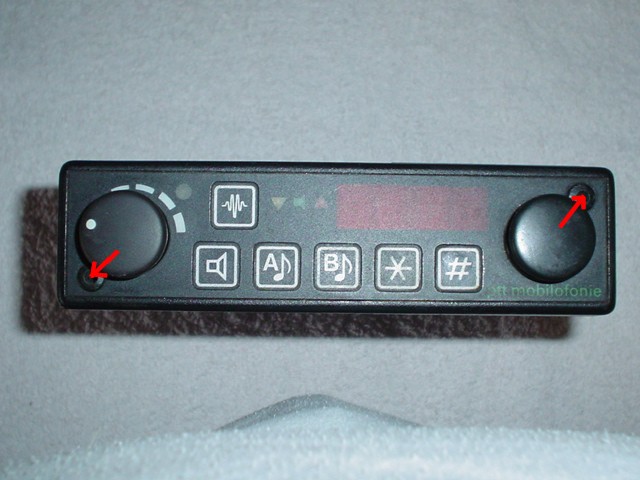
Now you can pull the head off
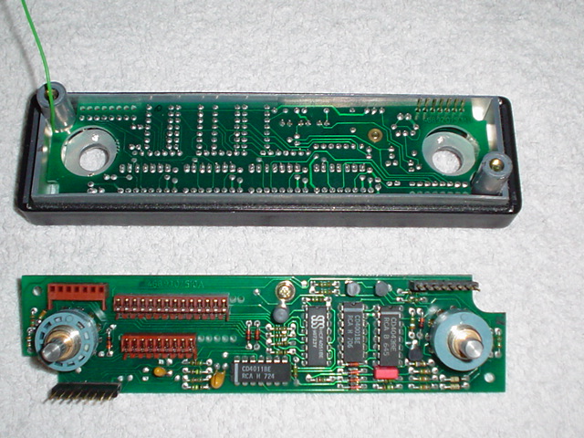
Take apart the boards
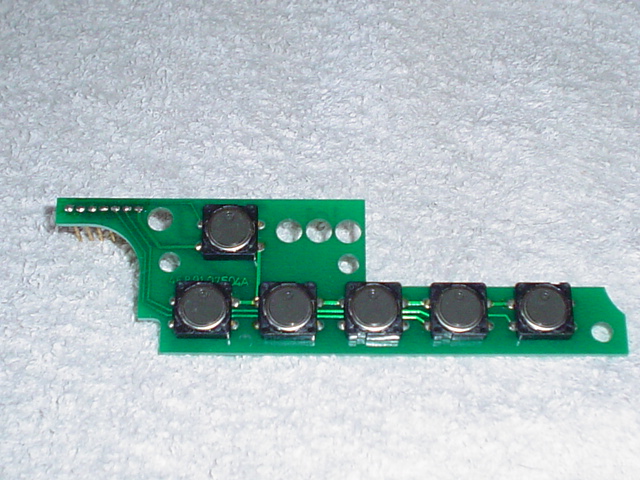
The head consists out of an operator front, and within there are 3 boards. Two of them you can remove carefully.
For removing the last board you have to do some things first. Carefully pull off the black knobs. Also remove the black scales underneath these knobs. Over the axles there are nuts, remove them as well. Turn around the casing and remove the three screws. Now you can remove the last board. On this board we put in the led's into the four corners of the switches. Now you have three boards and an empty casing. We are now going to work with the board on the bottom of the picture below.

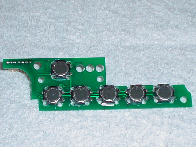
Drill holes for led's
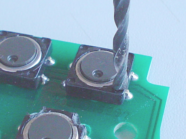
Be sure to clip on tight the board with the switches up worth. To make the holes you can use a small drilling machine with a 3 mm drill.
On the picture beneath you can see little dots in the corners of the switches. These dots we use to center the 3 mm drill

Drill all the holes on the switches. Be careful NOT to damage the switches, for they will not work when damaged.
After drilling the board looks like this:
Now you can clean the drilled holes with a sharp knife. When done you can fill the holes with the led's and do not need to be glued. After placing the led's the board looks like this:
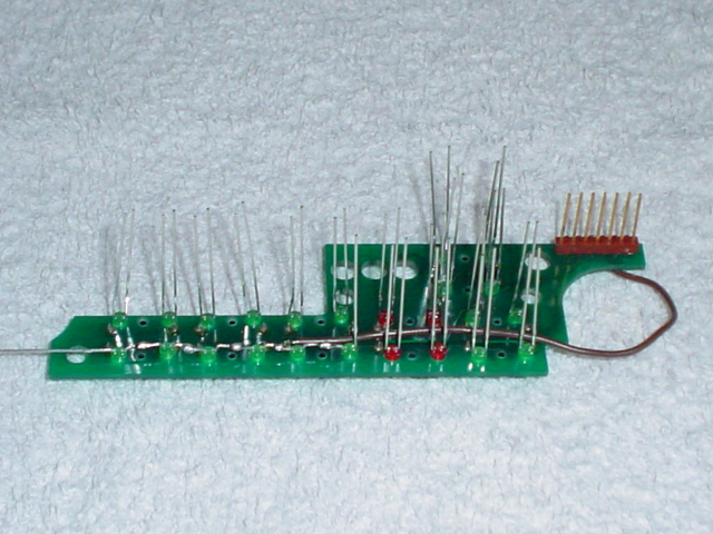
All the led's are placed in the same direction. The led's have a short (cathode = negative) and a long (anode = positive) leg.
Solder the Led's
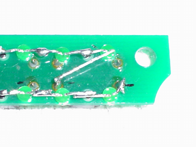
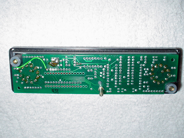
Now it's time to connect the led's together. Before we start we need to make some calculations. The connected voltage is 12 volts. The potential over the led's is in my case 2,2 Volts. (this varies per colour of led) 12 divided by 2,2 makes 5,45 led's. The car battery has a bit higher voltage, so it's safe to assume 6 led's are appropriate. We have to place 24 led's so we can configure 4 groups of 6 led's. Be sure to configure the led's in the right way from positive toward negative. So we start with the first led to connect ad the positive side (long leg) of 12 volts and end with a short leg (negative) at the negative side of 12 volt. After figuring out the solder job the board looks something like this:

On the picture above you see on the left side a brown wire. This wire is to compensate a penetration of copper circuit layer on the board while drilling the holes. This is NOT ALWAYS the case. Before soldering examine the board for penetrated circuit layer and repair it, if necessary, by placing a short wire.
Power feeds to the led's
So now we have 4 groups of 6 led's. Now it's time to make the power connections to these 4 groups. The 4 negative sides of the groups we can solder to the switches. With a universal meter we can check out which points on the switches can be used. All the switches have a main grounding. Solder the short remaining leg from each group op led's to that point.
Now we can make the power connection to the positive site of each group of led's. We can do this to combine the 4 long legs of the groups and connect this with ONE wire. This wire we connect in a later stage to the frequency board of the radio. Be sure to measure enough length and BE SURE there is NO short to the circuit board.
The board looks something like this:

When done we can test our connection by connecting 12 volts on to the wire, where positive is connected to the wire and the negative to the ground of the switches. All led's should illuminate.
Put the head together again
Put together the head in the reverse order as described in the first step.
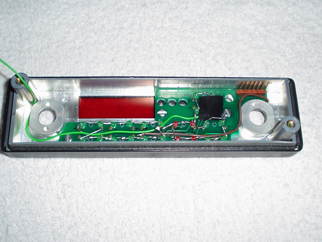
The black spot on the above picture is insulation tape to prevent short circuit to the next board.
As shown below, the positive power wire is in the corner.
The power wire is to be soldered on the first pin trough. That pin will be live (+12 Volt) AFTER THE NEXT MODIFICATION below.
Make modification
The head is now Finnished. The next modification must be made INSIDE the condor.
BEWARE !!! AFTER MODIFICATION NO UNMODIFIED HEAD CAN BE USED !!!
Take the condor remains.
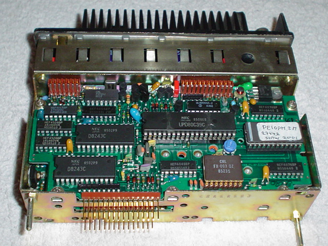
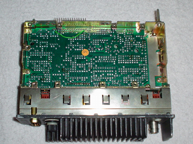
We have to modify the board in the middle, so we have to remove one board, mainly the HF board. For that we have to flip the body.

This HF board can be removed by loosening 8 screws. and pulling out the board.
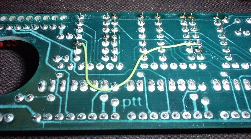
The modification consists of a connecting between two pins and interrupt an circuit trace on the board.
Place a wire connection between pin 15 (right hand) and pin 2. Then you cut the circuit trace on the board (see picture below)

All the NECESSARY modifications are made to illuminate the led's and the HF board can be replaced.
EXTRA modification; Khz indication on display
In the display you can see a decimal behind the frequency readout. For amateur use it is handy to distinguish between Mhz and Khz. This can be done to put a decimal on the right place in the frequency readout. This is simply done by placing a wire on de decimal of the last led segment to the decimal of the second led segment (see picture below).
This modification doesn't need explanation, just count the solder point on the picture.
These modifications has given me no problems what so ever, and is very convenient in the dark.
Thanks to PA3EKI en PE5SA
for their information on internet.